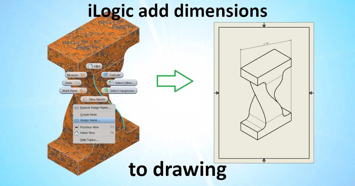


The company I work for has the policy that each drawing needs the overall dimensions of the part/assembly on the sheet. Years ago I created a tool that would generate the outer dimensions in a drawing view. It works okay, but I was not satisfied with the result. It is slow and there are edge cases in which you will get unexpected results. Last week I did have a new idea and wrote a new function. This new function works better!

In January (2021) I started reading about the Inventor update 2022. On the "Autodesk Inventor Customization forum" there was a topic by Adam Nagy warning us. The new feature "Modelstate" could affect some of the "Level Of Details" related functions. Till now I did not give it much thought. Probably I will not update for some years so I did not have to look at it.

Last week some one on the “Autodesk Inventor customization” forum asked the following:
“I have this code. It tends to work ok but I'm looking to improve the efficiency of the coding for future endeavours. I'm want to make a method for traversing the assembly and sub's so that it can be used over and over for all various traversing code I need to write.”

While writing iLogic rules I find my self often in the situation that I need to find a object in a list. Often I can use a standard Inventor api functions. But in some cases they do not work or the function just does not exists. For example I have the following situation. While generating drawings with our product configurator. An iLogic rule adds dimensions to an idw with many sheets. Ofcourse in that ILogic rule I need to select the correct sheet (in a list of sheets).

This is the last post in a sequence. In the first post of the sequence I discovered that it isn’t possible to assign names to faces in an assembly. I wanted that function therefore I decided to improve Logic. In this last post I will put it all together. And make it possible to create, view and use named faces of assemblies in a drawing.

Last week I created a class that will let you add labels to models. This week I created a rule to show/hide labels from named faces. To make this work we need to know which attributes are used for named faces.

In my previous post I showed how to create your own iLogic function “GetProxyIntent()”. With that function it’s possible to get curves from geometry in an assembly and create an intent for it. But as I mentioned to have a good workflow, we are still missing some tools.

In my previous post I discovered that it’s impossible to name geometry in an assembly. That also means that I can’t create dimensions from geometry in a assembly. There for I need a function that gets curves from geometry in a assembly and create an intent for it. With that i can create dimensions on an assembly drawing

At my job dimensions, on drawings, often get detached after and update by our configurator. One of the solutions would be creating the dimensions after the configurator finished. But creating dimensions with the Inventor API is difficult. Last November we upgraded to Inventor 2021 and I did read about the new iLogic functions. Last week I did have time to dive deeper in those new iLogic functions. This blog is about what I found.

I wish you all the best for 2021. I hope that we can go back to normal life this year. Today I have a iLogic rule for you that creates an “I” similar to the Inventor logo.

I’ve recently seen several questions from people looking to save or export files automatically. Questions like “How to perform ‘save a copy as’ PDF for a list of Inventor drawings from an excel?” and “Automate iPart flat pattern export to DXF”. That is why I wrote this post, explaining how you can write your own iLogic export rules.
Autodesk Inventor, Vault, Git, C#, vb, .net, php HTML, css, js
University computer science.
HBO Mechanical engineer.
MBO Fine mechanics.
Programmer and
Mechanical engineer
at Kelvion
(2016 - 20..)
Mechanical engineer
at Strukton
(2009 - 2016)
Mechanical engineer
at RDG-engineering
(2007 - 2009)
CNC Programmer
at VMC
(2005 - 2007)
volunteer
at Taizé
(2007)
Objectgeoriënteerd analyseren en ontwerpen, Objectgeoriënteerd programmeren in Java, Webapplicaties: de clientkant, Databases, Security Aware Programmer, Web Security Specialist